Modbus TCP
Modbus TCP lets you read a device's measured values directly over the network connection. The data does not have to pass through the cloud.
Requirements
To enable Modbus TCP, you need a smart-me Professional subscription
Supported devices
The following smart-me devices support Modbus TCP
Limitations
You cannot assign a fixed IP address. If you need one, set it on the router. smart-me does not know the MAC address of individual devices. You can find it using the instructions below.
Do not send queries more often than every 2 seconds. In some setups, a higher query frequency can cause queries to go unanswered. A query interval of < 2 seconds cannot damage the device.
Enabling Modbus TCP
-
Log in to the smart-me website.
-
Select the device.
-
Click the gear icon at the top right.
-
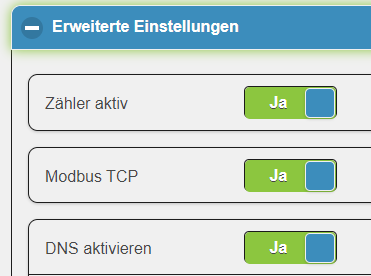
Under advanced settings (Erweiterte Einstellungen), enable Modbus-TCP
-
Save (Speichern)
Pico-specific information on Modbus TCP
You can use Modbus TCP with the Pico if:
-
The Pico is not in a load management group
-
The Pico is in a load management group and is the master (determined automatically)
Modbus TCP is disabled for all slaves in a load management group because they do not have their own IP address. We recommend using Modbus TCP only to control single devices without MESH. If you want to read or control Picos in a load management group, we recommend the Rest API.
Finding the device address
You can read the Modbus register of a smart-me device via DNS or via its IP address.
-
You can enable DNS in the portal.
-
The local DHCP server assigns the IP address. You can find the IP address using the following instructions.
Enabling DNS
-
Log in to the smart-me website.
-
Select the device.
-
Click the gear icon at the top right.
-
Under advanced settings (Erweiterte Einstellungen), enable DNS (DNS aktivieren).
-
In most cases, you need the internal IP. See below for details.
-
Save (Speichern)
-
The DNS name is shown in the text below Enable DNS (DNS aktivieren).
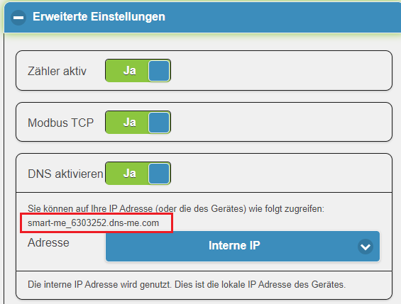
For the IP address, you can choose either a public IP address or the device's internal IP address:
Internal IP (Interne IP)
This is the local IP address of the smart-me device. You can use it if you are on the same network.
Public IP (Öffentliche IP)
This uses the public IP address. This is usually the IP address of your router.
Background information
The dns-me service lets you connect directly to a smart-me device without knowing its IP address. When DNS is enabled for a smart-me device, its local or public IP address is automatically mapped to a DNS name (e.g. smart-me_123456.dns-me.com).
smart-me uses the dns-me.com service for this.
Finding the IP address using the DNS name
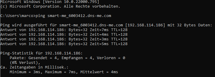
Once DNS is enabled, you can ping the DNS name shown in the advanced settings under DNS activation.
e.g. ping smart-me_6301587.dns-me.com
The ping response includes the IP address of the device.
Finding the IP address directly on the router
smart-me does not know the MAC address of individual devices. Without enabling the DNS service first, finding the IP address is therefore more complicated. One option is to query all IP addresses with Modbus TCP and check which serial numbers they return.
Data transfer
Modbus TCP protocol TCP port: 502
Functions The smart-me meter supports the following Modbus functions:
- Read Holding Register (Code 03)
Register addressing For historical reasons, the Modbus address is 1 lower than the internal register address. The start address must therefore be "register address - 1"
Modbus example
Example using: https://www.modbusdriver.com/modpoll.html
Change Pico Loadmanagement
modpoll.exe -r 0x206E -t 4:int -i -1 -m tcp -p 502 192.168.178.63 16000
Register addresses for smart-me meters and modules
Register Addressing
Register addresses for Pico charging stations
Pico-Modbus TCP
Controlling Pico load management with Modbus TCP
You can control a Pico charging station with Modbus TCP and set its charging current.
Firmware version < 0.0.53:
You can set the charging current once in mA for all three phases at the same time using register 0x206E.
Addressing a single station in a charging group (individual control):
-
- Only starts charging from the device's minimum setting, e.g. 6000 mA. The device tries to use as much of the available current as possible. In this case, the device charges 3-phase at 3x6A Single-phase charging cannot be specified explicitly. A single-phase vehicle is charged in 3-phase mode.
Addressing a station group with several stations:
-
Only the master device of the Pico group has an addressable IP address.
-
Only starts charging from the device's minimum setting, e.g. 6000 mA. With a group setting of 12000 mA With three active charging sessions: results in one single-phase charging session each at 12 A on L1, L2 and L3 With two active charging sessions: results in two 3-phase charging sessions at 6A With one active charging session: results in one 3-phase charging session at 12 A
From firmware version 0.0.53:
The charging current can be set:
-
For all three phases together in mA using register 0x206E (same value for all)
-
Together but individually per phase in mA or A (up to 499A; above that, mA is assumed) using register 0x2071
-
Individually, one phase after the other, in mA or A (up to 499A; above that, mA is assumed) using registers 0x2071, 0x 2073, 0x2075
General notes on the function:
-
On the controller side, limit switching between single-phase and 3-phase to once every 10 minutes.
-
You can switch to a predefined phase L1, L2 or L3 by specifying the available current. (The highest value is used)
-
You can switch between phases L1, L2 and L3 during a single-phase charging session. (Change of the highest current)
Important note on external control:
There is no limit on switching between individual phases, so make sure your control algorithm limits it. The same applies to switching from single-phase to 3-phase charging and vice versa. Heavy use of relay contacts can cause the relay switches to fail prematurely. We recommend not switching between individual phases if the additional power gained is not proportionate. Changeable weather, other large consumers and other factors can cause unintended switching. Ideally, a phase assignment should not change if the surplus is missing only briefly. smart-me accepts no responsibility for premature relay failure when third-party controllers are used.
Addressing a single station in a charging group (individual control):
-
-
Only starts charging from the device's minimum setting, e.g. 6000,6000,8000 mA. All three currents can have different values. The device tries to use as much of the available current as possible. In this case, the device charges 3-phase at 3x6A)
-
0,8000,0 mA results in a single-phase charging session at 8 A on L2
-
0, 8000 mA, 10000 mA results in a single-phase charging session at 10 A on L3
-
Addressing a station group with several stations:
-
Only the master device of the Pico group has an addressable IP address.
-
Only starts charging from the device's minimum setting, e.g. 6000,6000,8000 mA. All three currents can have a different value. The group tries to make the best possible use of the available current.
With one active charging session: one device charges 3-phase at 3x6A. With two active charging sessions: one device charges at 8A on phase L3 and the second at 6A on L2 or L1
-
0, 8000 mA, 10000 mA and two active units: results in one single-phase charging session at 10 A on L3 and another at 8 A on L2
-
0,16000,10000 mA and three active units: results in one single-phase charging session at 10 A on L3 and two single-phase charging sessions at 8 A each on L2
-
20000,20000,20000 mA and three active units: results in three 3-phase charging sessions, each between 6 and 7 A.