Input and Output Configuration
Configure inputs and outputs
smart-me meters have one or more outputs that can be used as a pulse output or as a potential-free contact. By default, the S0_0 output is set up as a pulse output and S1 as a digital relay output named "Relay" ("Relais").
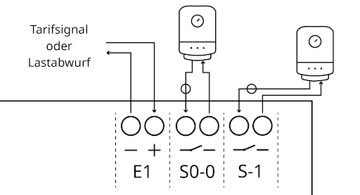
External wiring of the inputs and outputs
Controlling E1 with a tariff signal or load shedding
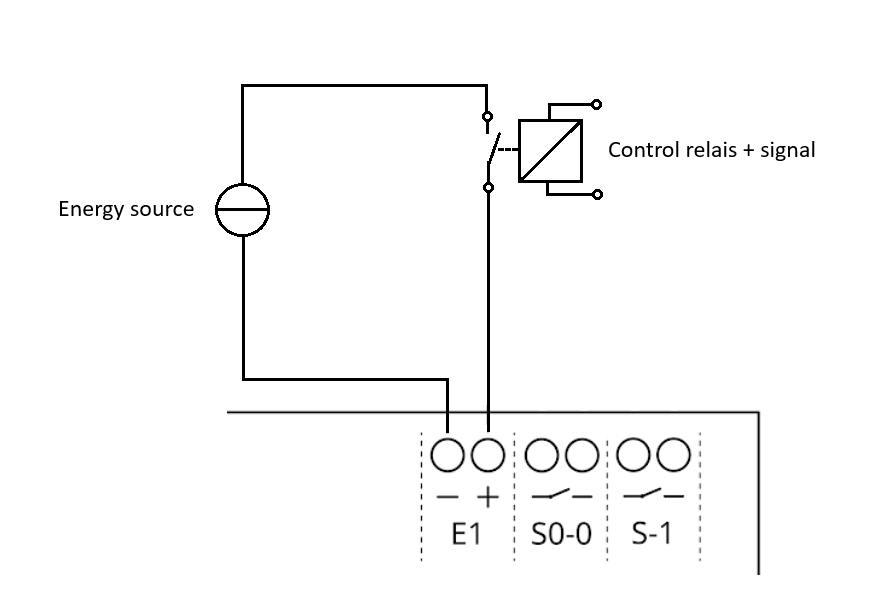
Circuit for switching on and off with Telstar (S1 and S0 are wired the same way)
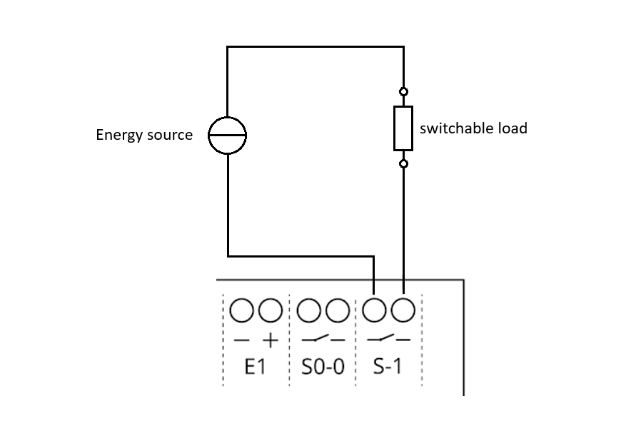
Pulse output
You can configure the output as a pulse output. You can choose between reactive energy and active energy.
Note: It is not possible to distinguish between consumption and feed-in. The absolute value is always output.
Configuration as a potential-free contact
If the output is set up as a potential-free contact, you can control any device via the smart-me Cloud. Control can be manual (on/off) or automated via event actions or if/then actions.
-
Log in to the smart-me website or the smart-me app
-
Select a meter and click "Edit" ("Editieren").
-
Under "Outputs" ("Ausgänge"), select the output you want and configure it as "Digital output" ("Digitaler Ausgang")
-
You can give the output any name you like.
-
You can define an action to be carried out if the meter loses its connection to the smart-me Cloud.
-
NOTE: If S1 is not used as a digital output, you can also hide it from the view by switching it to pulse output. In the tenant view, these outputs cannot be switched on or off, even if they are visible there.
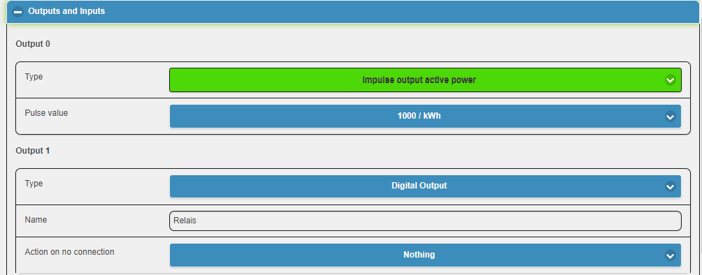
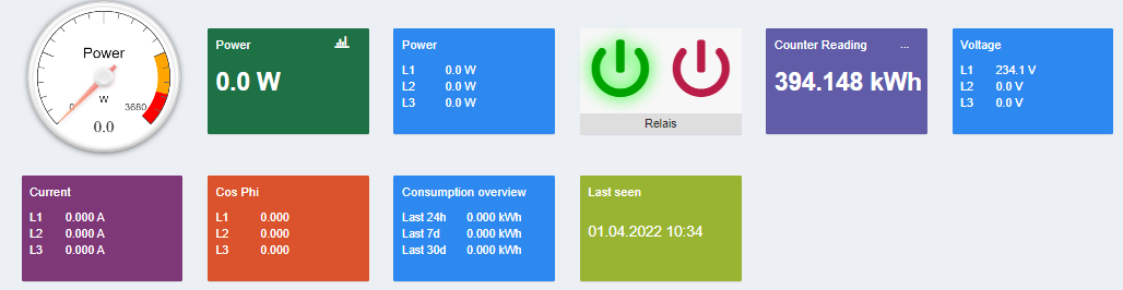
Online view when commissioning a Telstar 80A or CT
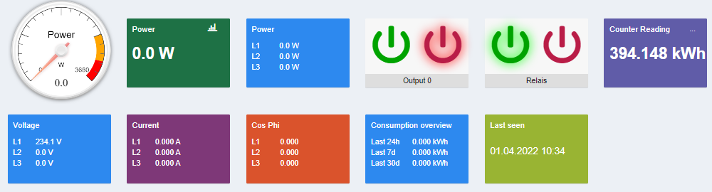
Online view after activating S0_0 as a digital output
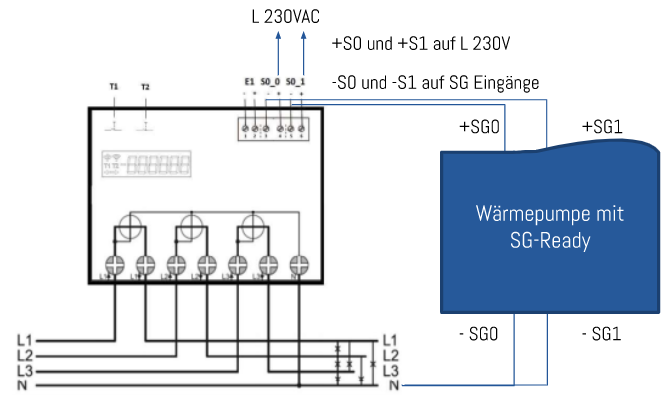
Wiring the outputs
Observe the maximum voltage, current and power ratings of each output. To put it simply, you can think of each potential-free output as an unconnected switch. For it to work, there must be a circuit from high to low potential.
The outputs do not supply any voltage themselves, so a voltage source must be connected upstream.
For 230V AC circuits:
-
230 VAC to the "+" contact of S1
-
Wire the "-" contact of S1 to the "+" input of the external circuit.
-
Finally, connect the "-" of the external circuit to the neutral conductor. (No resistive load needs to be connected)
For DC circuits:
-
from + VDC to the "+" contact of S1
-
Wire the "-" contact of S1 to the "+" input of the external circuit.
-
Finally, connect the "-" of the external circuit to GND.

*Depending on the device type
Configure the input
smart-me meters have a digital input that can be used as a tariff input or as a standard digital input. By default, this input is set up as a tariff input. If you configure the input as a digital input, you can use it as an event to control other devices or trigger alarms. If the input is set up as a tariff input, metering switches from tariff 1 to tariff 2 when voltage is applied.
Configuration as a digital input
To configure an input as a digital input, proceed as follows:
-
Log in to the smart-me website or the smart-me app.
-
Select a meter and click "Edit" ("Editieren").
-
Under "Inputs and outputs" ("Eingänge und Ausgänge"), configure the input as "Digital input" ("Digitaler Eingang")
-
You can give the input any name you like.
-
You can define a text to be shown when the input is "On" ("Ein") or "Off" ("Aus").
-
-
You will now see the digital input and its status in the smart-me app and on the smart-me web portal.
Using the digital input for control
You can use the digital input to switch other devices or send alarms. To do this, define the "Switching state" ("Schaltzustand") if-event under if/then actions.
Wiring the connection
To switch the potential-free contact, an external voltage and potential (e.g. neutral conductor) must be applied. You can find the voltage values in the technical data of each product.
Logic: 1 (High) = voltage according to data sheet 0 (Low) = 0 volts
Note: With DC voltage, pay attention to the polarity (E1+/E1-). With AC voltage, polarity does not matter.