Configure multilevel load management
Configuring dynamic multilevel load management (MLM)
Multilevel load management is configured in the "Multilevel Load Management" ("Multilevel Lastmanagement") area of the main navigation.
The function enables:
-
Dynamic control of multiple static Pico charging groups
-
Limiting the charging power to reference points within the installation or the site
-
Solar optimization
-
Peak load reduction
-
Charging group prioritization

Definition of terms
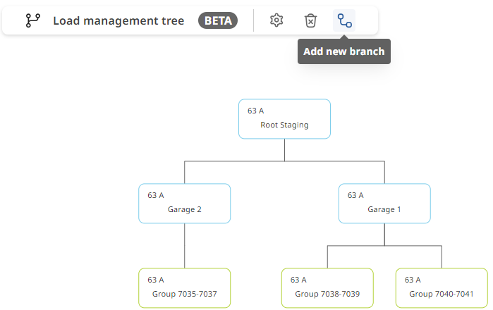
Multilevel load management can be viewed as a tree, with the following terms and uses:
-
Trunk (main connection point of the installation)
-
Branches (limiting points such as junctions, building connections, sub-distribution boards, aggregate outgoing circuits)
-
Leaves (static Pico charging groups)
The trunk and the branches can take on several functions:
-
Current limiting (maximum fuse rating)
-
Solar optimization ON or OFF
-
Unmeasured loads present (active or inactive)
Unmeasured loads:
An unmeasured load is a producer or consumer that is not a Pico charging station group. To take this production or load into account dynamically, meter hardware must be provided as a reference. (Measured branch)
The branch can also be limited statically without a reference meter, but it must then be restricted to a functional maximum of the fuse rating that takes the base load into account.
Typical branches with unmeasured loads:
-
Building connections (apartments, solar systems, battery storage, outdoor lighting)
-
Sub-distribution boards (interconnection of several building complexes, SDB East, SDB West,...)
-
E-mobility outgoing circuits (Pico standby consumption and garage lighting)
Adding or deleting a branch
Adding:
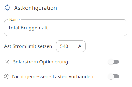
Select the trunk or a branch and use "Add branch" ("Ast hinzufügen") to create an additional branch or junction.
Deleting:
Selecting the relevant branch and using the "Delete" ("Löschen") function deletes the selected branch and all branches attached to it.
To keep the elements below it, the branches and groups can first be attached to another branch or to the trunk using drag & drop.
Adding charging station groups to the tree
The charging station groups that are not yet assigned and are correctly configured for the MLM are located on the right-hand side.
They can be attached to the branches using drag & drop and can also be moved within the configuration using drag & drop.
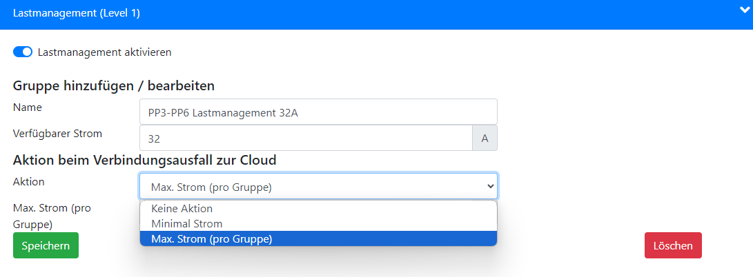
Note: A prerequisite for use in the MLM is that the connection loss setting is configured to "Max. current (per group)" ("Max. Strom (pro Gruppe)").
This can be adjusted on a Pico charging station under "Configuration" ("Konfiguration").

Solar optimization and minimum current per charging group
Branch configuration:
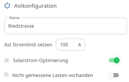
Solar optimization is possible once on the trunk (site-optimized) or several times in parallel on branches with active unmeasured loads, e.g. building connections.
Depending on the choice, the solar surplus is optimized across all charging station groups or only across some of the charging station groups.
Group configuration:
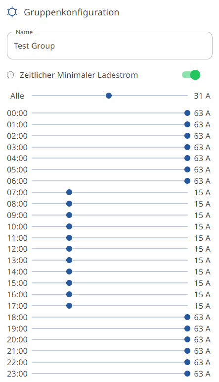
For solar optimization to have the intended effect, the station groups to be optimized must temporarily be assigned a reduced minimum charging current. This minimum charging current is defined on the relevant charging group (group configuration) and corresponds to the maximum possible grid consumption for the charging group during the defined hours.
At the same time, setting the minimum charging current can also be used for peak shaving.
Each group can be configured differently.
Groups with a higher minimum charging current are prioritized when available grid current is distributed.
Saving and activating the configuration
Changes to the configuration are only saved if the configuration is also activated.
If activation cannot be carried out because of misconfigurations, this may be due to the following points:
-
The charging group is not correctly configured for the MLM (the internet loss setting is not set to Max. current per group)
-
Individual devices relevant to the MLM are not online at the time of saving. (bring them online)

Deleting the MLM configuration
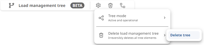
The entire configuration of an MLM can be deleted at the push of a button in order to create a new configuration.
Configuring load shedding
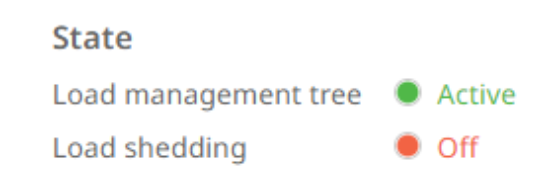
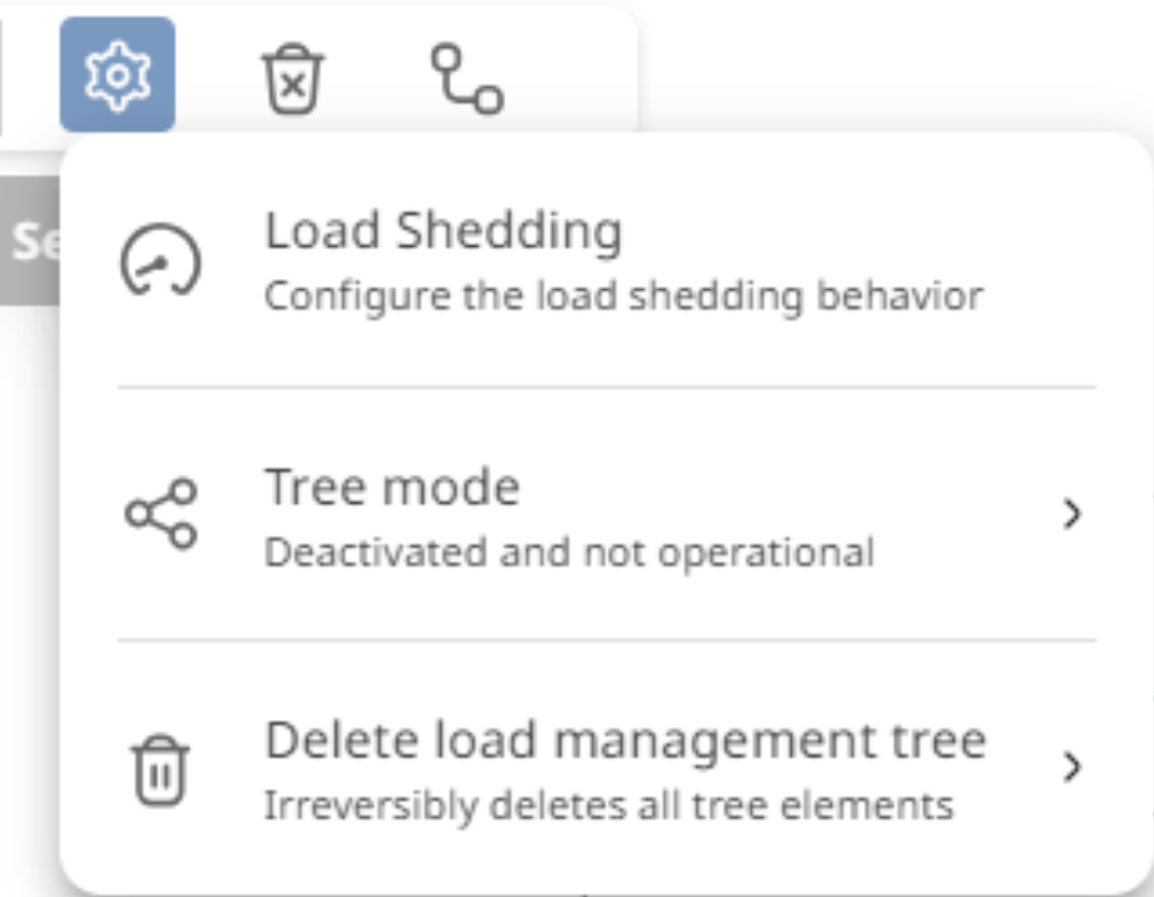
The MLM has an integrated load shedding control.
This control can be used instead of the hardware inputs on the back of the Pico charging stations.
Notes:
-
Signals connected directly to Pico hardware cannot be overridden with this function.
-
The function requires an active internet connection to work. If the internet connection is lost, the configured internet loss value of the Pico groups is used.
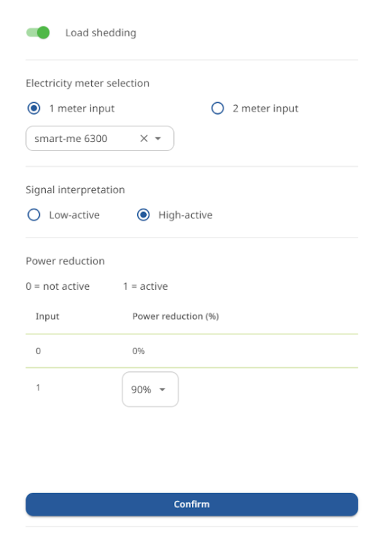
The function makes it possible to interpret one or more digital signals from energy suppliers and to allocate a reduced charging power to all charging station groups of the MLM.
The control signals are wired to one or two nearby meter inputs (E1).
smart-me Telstar CT and Telstar 80A hardware are compatible for this purpose.
Note: For the inputs to be usable, they must be configured as "Digital input" ("Digitaler Eingang") on the hardware side. (Meter settings, E1 --> Digital input)
Control configurations:
With only one signal:
- 1-stage: 0% reduction, variable reduction (10-100%)
With two signals:
-
4-stage: 0% reduction, variable reduction, variable reduction, 100% reduction
-
3-stage: 0% reduction, variable reduction (both at the same level), 100% reduction
Applying the percentages to EnWG14a in Germany:
-
For 22kW installations, a reduction of 82% corresponds to the guarantee of 4200W minimum power per device in the installation.
-
For 11kW installations, a reduction of 73% corresponds to the guarantee of 4200W minimum power per device in the installation.
Signal interpretation:
The signal can be interpreted in different ways.
If the energy supplier removes the signal in the event of load shedding (230V --> 0V), "Low active" ("Low-Aktiv") is the correct configuration.
No signal (0) = 1 = available energy is reduced
If the energy supplier applies the signal in the event of load shedding (0V --> 230V), select "High active" ("High-Aktiv").
Signal (1) = 1 = available energy is reduced.
Activating and deactivating the MLM processor
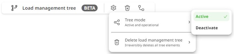
The MLM configuration can be deactivated and reactivated at any time.
-
Stops the calculation process and the active allocation of values from reference points.
-
Gives all subordinate load groups the defined internet loss value for free use.
Set the value to active or inactive and then save the configuration to pass it on to the processor.
Example configuration: house with e-mobility outgoing circuit + garage lighting, solar system and midday peak smoothing
-
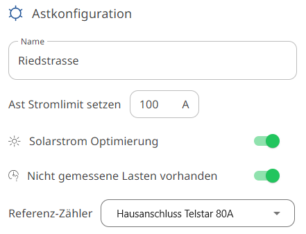
Here the trunk corresponds to the building connection
-
The fuse rating of the connection is 100A per phase.
-
Solar optimization is located on the building connection here.
-
The solar system production and the building's own consumption are measured and taken into account with the meter "House connection Telstar 80A" ("Hausanschluss Telstar 80A").

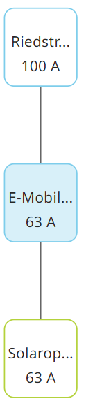
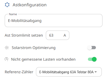
The subordinate e-mobility outgoing circuit is actively measured here to take the garage lighting into account. This allows the charging groups to react dynamically to the garage lighting.
-
The garage lighting is taken into account with the reference meter "E-mobility outgoing circuit 63A Telstar 80A" ("E-Mobilitätsabgang 63A Telstar 80A").
-
The fuse rating of the outgoing circuit is 63A per phase.
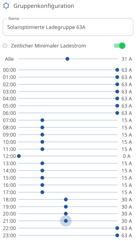
For solar optimization to take effect, the minimum amount of charging current is reduced during the day.
-
The minimum amount of current corresponds to the maximum possible grid consumption at the defined hour.
-
As soon as the solar system covers 100% of the minimum amount of current, the stations additionally receive the extra surplus from the solar system.
-
Solar optimization for the whole week from 6:00 to 17:00, minimum charging current of 15A per phase
-
Midday peak smoothing: charging from 12:00 to 13:00 is only possible with solar surplus, grid consumption remains at 0A
-
Night-time charging from 18:00 to 22:00 is possible at 50% capacity.
-
Night-time charging from 22:00 until 7:00 in the morning is possible at 100% capacity. (e.g. making full use of the off-peak tariff)

Example configuration: site with several houses, solar systems and e-mobility outgoing circuits
-
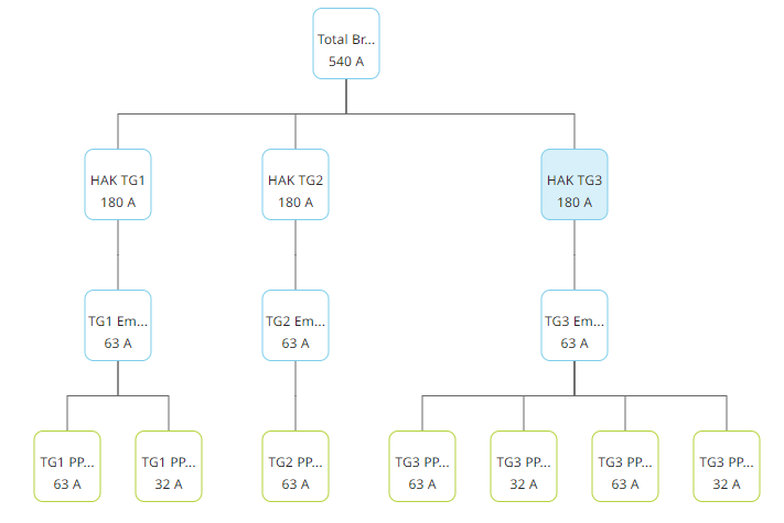
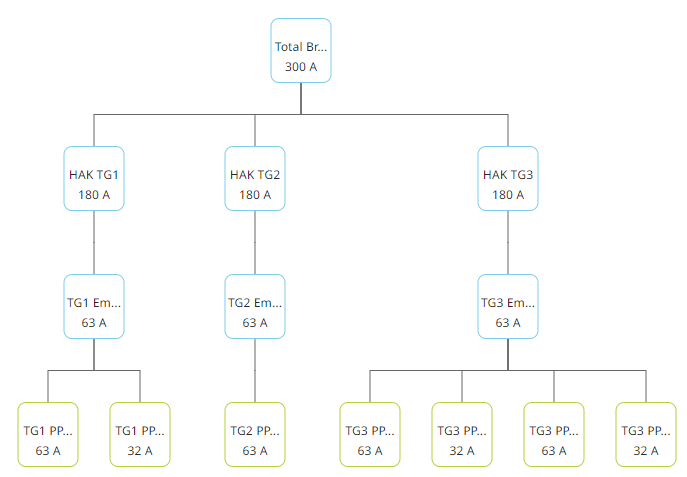
ZEV (association for own consumption) site with 3 houses
-
Each house has an underground car park
-
Several charging groups in underground car parks
-
TG1 has outdoor parking spaces for visitors as well as tenant parking spaces
-
Houses TG1 and TG2 have solar systems
-
Solar optimization on the site so that TG3 can also benefit from solar energy.
-
Site fuse rating 300A per phase
-
House fuse ratings 180A per phase
-
E-mobility outgoing circuits 63 A or 32A per phase
-
The ampere value corresponds to the fuse rating of the supply line
-
The measuring point is fused but not measured itself. Since all subsequent branches have measurements and these correspond to 100% of the site's consumption, the trunk can be limited virtually.
-
Solar power optimization on the trunk (site) active. (Availability of solar power for all three houses)

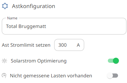
HAK TG1: building connection of building 1 on the site
-
Fuse rating 180A per phase
-
Unmeasured loads active: apartments, heating, lighting, general, solar
-
Dynamic consideration of the apartments and heat pumps

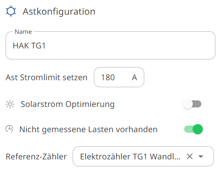
TG1 e-mobility outgoing circuit
-
Fuse rating 63A per phase
-
Unmeasured loads active: garage lighting and ventilation in addition to the EV charging stations
-
Dynamic consideration of the garage lighting and ventilation

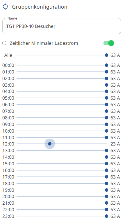
Visitor parking spaces on the site (public charging stations)
-
High energy availability and prioritization at a higher selling price. Published via the eCarUp backend. (Backend authentication)
-
Permanently 100% of the possible capacity from the grid + solar coverage.
-
Midday peak shaving from 12:00 to 13:00, only 23A per phase from the grid + solar surplus.
-
Cable fuse rating 63A per phase

Tenant parking spaces on the site
-
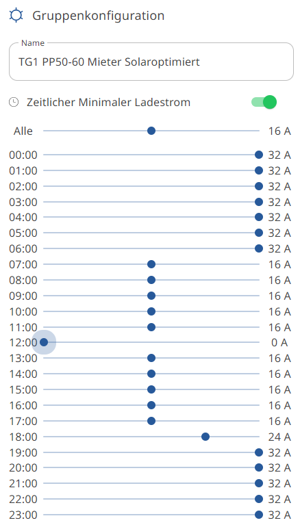
Medium energy availability and prioritization, focus on solar energy during the day.
-
Permanently 50% of the possible capacity from the grid.
-
Cable fuse rating 32A per phase.
-
Midday peak shaving 0A from 12:00 to 13:00. Only solar charging possible if the production is not used by the site for other purposes.

Parts of the installation not covered:
-
The building connections and e-mobility outgoing circuits of houses 2 and 3 are configured in the same way.
-
The 4 charging groups in underground car park 3 (TG3) are configured similarly to the tenant parking spaces in underground car park 1 (TG1)
-
Each charging group can have its own behaviour and can also receive different emergency supply currents in the event of an internet outage.