Multilevel load management
Webinar multilevel load management (50 min)
Technical requirements for using multilevel load management
-
Pico firmware version 0.0.25 or higher --> Perform firmware upgrade
-
All if/then rules involving Pico have been deleted so that no commands contradicting the MLM are sent.
-
As of: 12.03.2024 No support for load shedding via Telstar input contacts --> release of the solution in MLM will follow.
-
Load management only works with Telstar CT / Telstar 80A or Nimbus
Dynamic multilevel load management
Dynamic multilevel load management coordinates the limiting and dynamic capabilities of the individual load groups at building connection and site level.
Its task is to make the remaining free current capacity at each reference point available to the subordinate load groups, thereby protecting the branch points against overload.
Examples of important branch points:
-
Site connection
-
Building connection
-
Sub-distribution feeder
-
Garage outgoing feeder
At the same time, multilevel load management enables solar optimization and offers functions for peak load smoothing.
Limits of dynamic multilevel load management:
-
Max. 1000 devices (charging stations + reference meters)
-
Max. 50 branches (reference points)
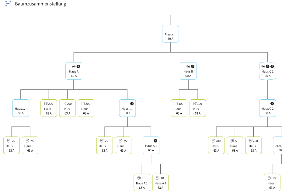
Overload protection of the branch points (site connection, sub-distributions, building connection)
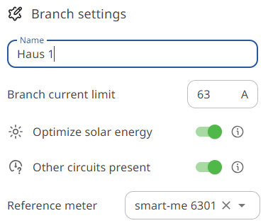
Maximum current values can be defined for all branches created in multilevel load management. These act as an absolute upper limit for current consumption and correspond to the fuse rating of the feeders.
A branch can only exist according to the following scheme:
-
Branch with "unmetered loads": There are other consumers or producers behind this branch that are not exclusively Pico groups. A reference meter is required to determine them.
-
Branch without "unmetered loads", virtual: The downstream consumers consist exclusively of Pico load groups or of "branches with unmetered loads" and the corresponding reference meter. The total current can therefore be calculated from the sum of these available measurements and corresponds to 100% of the current to be controlled.
Areas of application: - Limiting the total site current by means of metered sub-distributions (saves a site meter) - Protecting several branching flat ribbon cables from one fused outgoing feeder
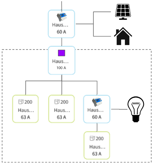
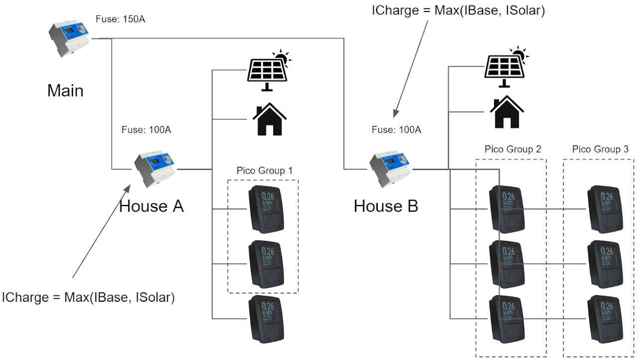
Virtual branch (purple) limits on the basis of the branch with unmetered loads and Pico groups.
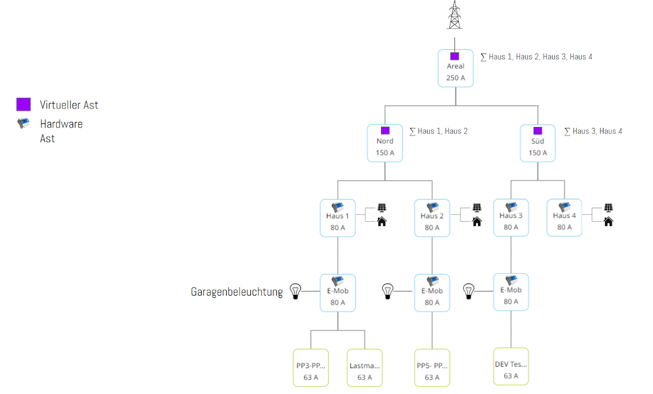
Example setup of a housing development with MLM
Solar optimization
Solar optimization enables efficient allocation of surplus electricity to the subordinate Pico charging groups. This requires at least one "branch with unmetered loads" and the corresponding reference meter.
The optimization can only take place once in series (tree from top to bottom) or several times in parallel branches.
This allows solar optimization to be implemented for the entire site or just for specific buildings.
Example:
-
Site optimization: solar optimization active on the branch, referencing the site meter or a virtually created branch based on the metered sub-branches.
-
Building optimization: solar optimization active on several branches, referencing the respective building meters.
With solar optimization on the site connection, surplus produced in building B is also available to the charging infrastructure in building A.
Minimum charging current: indirect prioritization and peak load smoothing
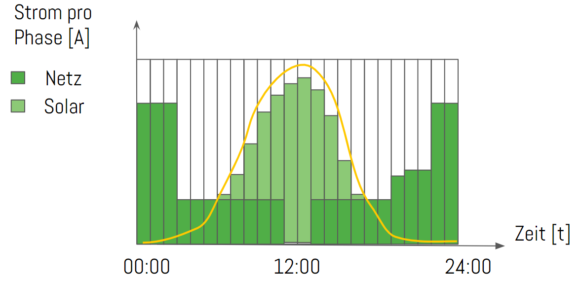
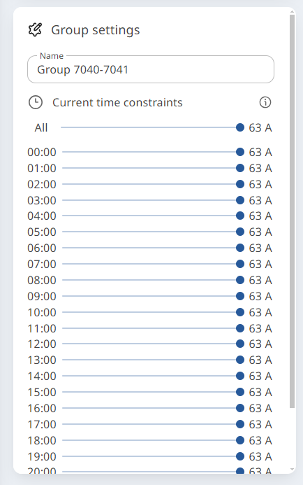
Each individual Pico load group can be assigned a time-dependent minimum charging current.
The setting is made flexibly for each hour of the day.
This function makes it possible to provide a minimum charging current independently of other parallel optimizations.
Only an exceeded current limit of a branch would have an opposing effect on it.
As long as the minimum charging current can be guaranteed, it limits direct grid consumption to the set level.
If solar optimization is present, however, the available charging current can rise above the set minimum and is increased accordingly.
Example applications:
Reduce charging current during production hours to reduce load peaks.
Reduce charging current at midday to reduce load peaks.
Reduce charging current during the day to achieve a higher prioritization of solar power.
Giving preference to outdoor parking groups over underground car park spaces (group prioritization)
Prioritization
Setting the available minimum current of a group implies a certain priority over the other charging station groups. The charging station group with the higher available minimum current at the given time is always given preference by the algorithm.
Example:
26 A per phase are currently available for distribution in the MLM: Charging group A: minimum current = 10A Charging group B: minimum current = 20A
Charging group B is supplied with 20A first and charging group A receives the rest.
Behavior of multilevel load management during an internet outage
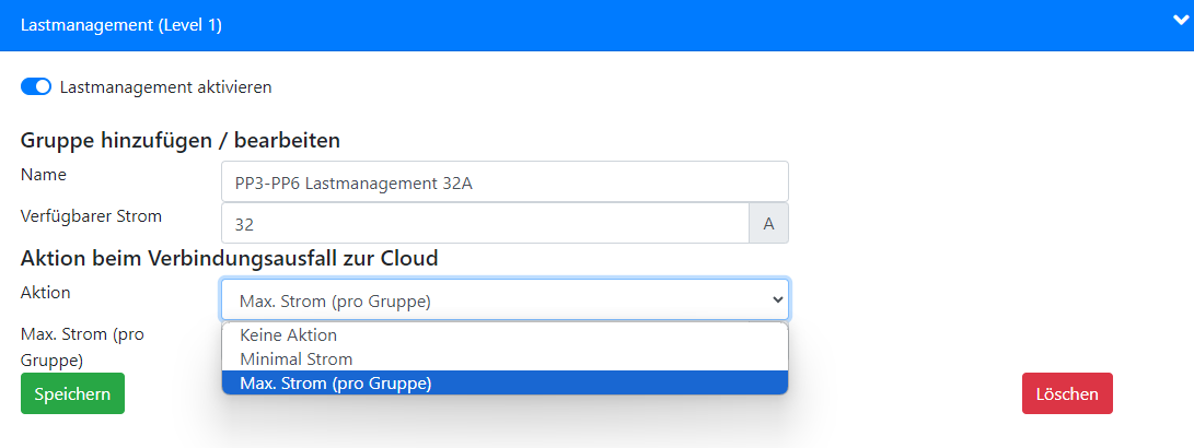
All Pico charging stations must be set to the connection loss setting "Max. current (per group)" ("Max. Strom (pro Gruppe)"). The other two modes are only permitted for standalone operation.
Function: Charging groups affected by internet loss are regulated back to the level defined for the group. The current is distributed automatically by the charge manager, taking the active charging sessions into account. Multilevel load management assumes that the lost branches draw the defined group current and deducts this from the available remaining current.
The functioning part of the installation with an active internet connection continues to operate in normal mode with this defined restriction.
Load shedding with MLM
Load shedding can be implemented in various ways using the ripple control signal (RSE) of the energy supplier.
-
Pico hardware inputs on the rear for transmission to one Pico group.
-
Signal on meter inputs and transmission via MLM to all load groups.
More information under
Configuring load shedding with MLM
Configuring load shedding via external inputs
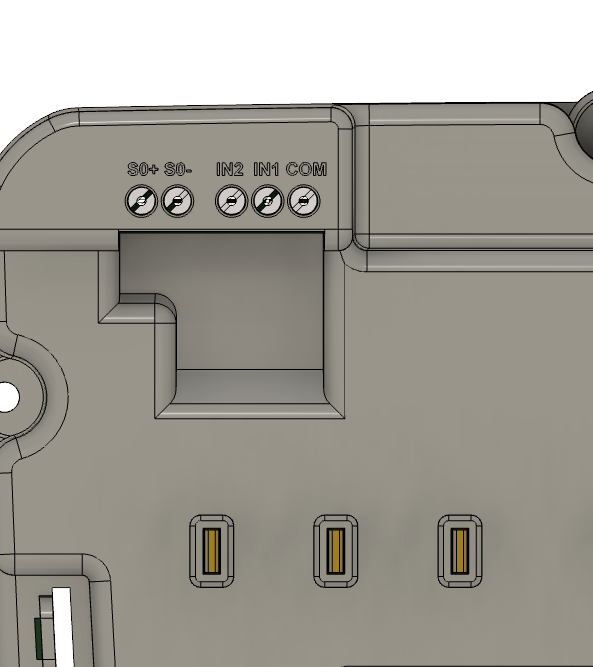
Pico hardware inputs
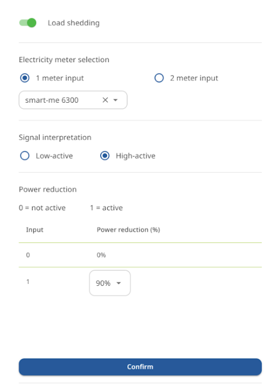
Cloud-based load shedding (MLM)
Limits of multilevel load management
Maximum number of Picos and reference meter points: 1000
Maximum number of virtual and hardware reference points: 50, 6 in series
Maximum size of an individual charging station group: 200 charging stations
Minimum number of Picos per charging station group: 1
Minimum number of reference points in the MLM: 1 (hardware or virtual)
Maximum number of charging groups: 60 groups
Examples of minimum configurations:
- 1 outgoing feeder with 1-200 charging stations incl. 1 reference point
Examples of a typical maximum configuration:
-
60 outgoing feeders with 16 charging stations each incl. 8 reference points can be created. (Large housing developments with ZEV)
-
6 outgoing feeders with 150 stations each incl. 50 reference points (public parking complexes)
-
4 outgoing feeders with 200 stations each incl. 50 reference points (public parking complexes)